
1
/
von
1
Linde
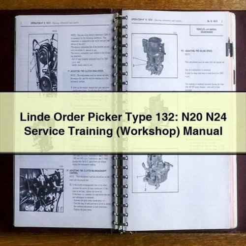
Linde Order Picker Type 132: N20 N24 Service Training (Workshop) Manual
Linde Order Picker Type 132: N20 N24 Service Training (Workshop) Manual
Normaler Preis
$16.99
Normaler Preis
Verkaufspreis
$16.99
Versand wird beim Checkout berechnet
Vehicle data plateRef 68889
- Brand
- Linde
- Vehicle
- Material Handling
- Models covered
- N20, N24, Order Pickers
- Format
- PDF, searchable, print-ready
- Delivery
- Instant download after checkout
- Language
- English
Verfügbarkeit für Abholungen konnte nicht geladen werden
What happens after you pay
- Download link opens on the order page immediately
- The same link is emailed to you — re-download any time
- Open on phone, tablet or PC; print only the pages you need
- Not sure it covers your model year? Ask us before you buy
Original Illustrated Factory Service Training (Workshop) Manual for Linde Order Picker Type 132.
Original factory manuals for Linde Forklift Trucks, contains high quality images, circuit diagrams and instructions to help you to operate and repair your truck
Covered models:
N20
N24
Format: PDF, 192 Pages
Language: English
Contents:
0. Product information
Description
Order picker N20-N24 Type 132
Diagnostics
Accessing truckinformation
Can Bus Network
Multi-function indicator, breakdown code display
Breakdown code descriptions
TRACTION fault codes
LIFT fault codes
Fault codes -STEERING -Main Controller
Fault codes -STEERING -Safety Controller
1. Motor
Traction motor
Description
Removing the drive motor
2. Drive - Transmission
Drive unit
Description of the drive unit
Removal/replacement of the drive unit
Reducer
Gear reducer
Reducer unit
Removal/ refitting reducer gearbox
3. Truck
Battery compartment
Battery removed vertically or from the side (option)
Battery removed from the side
Platform and technical compartment access
Dashboard console and technical compartment covers
Chassis equipment
Height adjustable seat
Driving platform
Platform floor
Removing the drive platform
4. Steering, braking and wheels
Electrical steering
General
Support with height-adjustable handlebar controls
Control handlebar
Removing the handlebar
Steering centre (LORD)
Steering geared motor
Removal/replacement of the steering motoreducer
Wheel position potentiometer (3B3)
Steering motor (3M1)
Electric steering adjustment
Brake
Hydraulically assisted electromagnetic parking brake
Wheels
Rolling bases
Drivewheel
Height adjustable fixed stabiliser
Controllable stabilisers
Stabilising wheels (suspended stabilisers)
Load bearing wheels
5. Control apparatus
Pedestrian control (option)
Slow approach buttons 1S10-1S11 -1S12-1S13
6. Electrical equipment
N20-N24 type 132
General
Truck operation N20-N24type 132
Location of connectors
Electrical panel
Manipulating the electrical plate
Fuse access
Traction (L. A.C. 03)
Traction and hydraulic controller -LAC 03/ 1A1
Functions of the "Inputs/ Outputs" of the LAC 03
Turning on the LAC Controller- 1A1
Replacing the L.A.C. box (1A1)
Setting up the control module (1A1)
Accelerator (1S21, 1S22) and potentiometer (1B1) controls
Horn4H1
Hydraulically assisted electromagnetic brake Y1
Traction motor speed sensor 1B2
Monitoring traction motor temperature 1B6
Battery locking sensor 1S1 9
Controlling the LAC cooling fan 9M1
Speed restriction n°1 and n°2 (options)
Hydraulic controls
Operation of the initial lift (2M1)
High fork end-of-travel 1 B4
Initial lift lowering function 2Y2
Hydraulic stabiliser control (option)
Inclinometer 1A8
Stabiliser solenoid valves 2Y8 and 2Y9
Electrical steering (L.E.S. 40
Electric steering controller L.E.S./3A1
Functions of the "Inputs/ Outputs," LES(3A1)
Replacing the L.E.S. box (3A1)
Setting steering control module parameters (3A1)
LES Controller power up
Speed reduction when turning (with LAC n°390 360 85 19)
Multifunction indicator (Bauser)
4-button multifunction indicator (version CAN BUS)
Programming the multifunction indicator
Changing the multifunction display
Using PathFinderto set multifunction indicator parameters
Replacing the key (S1) with a DIGICODE
7. Hydraulic assembly
Hydraulic equipment
Description
Hydraulic circuits
Stabiliser hydraulic circuit
Draining the stabiliser hydraulic circuit
Liftingjack hydraulic circuits
8. Lifting system
Initial lift
Initial lift guidance
Annex
10. DIAGRAMS
Circuit diagrams
Power schematic
Electrical control schematic N20 - N24 (LAC), 4 point chassis
Electrical control schematic N20 - N24 (LAC), 5 point chassis
Hydraulic diagrams
Main hydraulic diagram
Hydraulic diagram for stabilisers
Delivery & file format
Delivery & file format
This is a digital PDF download, not a printed book. After payment the download link appears on your order confirmation page and is emailed to the address you entered. Files open in any PDF reader on phone, tablet or computer and can be printed.
Check the model year and engine before you buy
Check the model year and engine before you buy
Manufacturers change procedures, wiring and part numbers between model years and engine options. If your VIN plate shows a year or engine code that is not listed on the data plate above, contact us with the model, year and VIN and we will confirm coverage before you order.
Share

Linde Order Picker Type 132: N20 N24 Service Training (Workshop) Manual
Linde / Order Picker · PDF · Instant download
$16.99
- Instant download Link on the order page and in your inbox within a minute.
- Secure checkout Encrypted Shopify payments — card, PayPal, Apple Pay, Google Pay.
- Print-ready PDF Searchable text; print only the pages you take to the bench.
- Coverage check Not sure it fits? Send the model and VIN before you buy.
