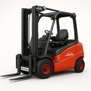
Linde Electric Forklift Truck 387 Series: E20 E25 E30 E35 Service Training Manual PDF Download
Original Illustrated Factory Workshop Service Manual for Linde Electric Lift Truck 387 Series. Original factory manuals for Linde Forklift Trucks, contains high quality images, circuit diagrams and i...
One-time purchase - Lifetime access
Instant Download
Get access immediately
Secure Payment
SSL encrypted checkout
24/7 Support
Help when you need it
Money Back
30-day guarantee
What's Included
Complete Service Manual
Full PDF documentation
Step-by-Step Procedures
With detailed diagrams
Wiring Diagrams
Electrical schematics included
Specifications
Torque values & specs
Troubleshooting Guides
Diagnostic procedures
Lifetime Access
Download anytime
Original factory manuals for Linde Forklift Trucks, contains high quality images, circuit diagrams and instructions to help you to operate and repair your truck
Covered models:
E20
E25
E30
E35
Format: PDF, 582 Pages
Language: English
Contents:
0. Product information
Technical data
Type overview
Serial numbers
Inspection and maintenance
Service overview
Activities within scope of service
Operating materials
Lubricants and operating materials
Tightening torques
Tightening torques for standard pitch threads
Tightening torques for fine pitch threads
Tightening torques for units
Special tools
Special tools and measuring instruments
Diagnostics
Overview
Canbox
Software update for Canbox
Pathfinder
Log files
Code lists
Error code display
Driving codes
Working hydraulics codes
Traction power module codes
Working hydraulics power module codes
Codes display
Battery charger codes
1. Motor
Drive axle
Overview
Drive axle plug positions
Spring elements
Planetary transmission breather
Axle housing checking screw
Special tools, drive axle
Removingthe drive axle
Dismantling the drive axle
Install the drive axle
Traction motor
Technical data
Changing bearings and shaft seal
Motor testing
Preparation
Visual inspection
Traction motor winding test
Rotor testing
Motor connection
Power module connections
Cleaning
Cleaning the motor - drive axle
Sensors
Rev sensor
Drive axle temperature sensor
Forced ventilation
Overview
Changing the fan
2. Drive wheel unit
Planetary transmission
Functional description
Changing the shaft seal
Planetary transmission Checking the oil level
Changing the oil in the planetary transmission
3. Chassis, bodywork and fittings
Chassis
Chassis design
Locking bolt setting
Front panellings
Rear panelling
Driver's seat
Changing the seat switch and switch plate
4. Chassis frame
Steering system
Functional description
Steering actuation
Steering column
Steering control valve
Combined axle
Functional description
Removing the combined axle
Removing the steering cylinder and tie rod
Changing the steering cylinder seals
Installing the steering cylinder and tie rod
Exchanging the tapered roller bearing and wiper of the axle beam casing
Exchanging the tapered roller bearing and shaft seal on the axle stub
Installing the combined axle
Adjusting the steering lock
Steering angle sensor
Steering angle sensor 3B1
Changing the steering angle sensor
5. Operating devices
Accelerator
Function
Exchange
Stop screws
Brake system
General
Electric brake
Functional description
Stop pedal sensor
Hydraulic service brake
Functional description
Brake valve
Brake valve purge function
Towing
Joysticks
Joystick configurations
Joystick variants
Joystick interlock
Functional description
Exchange
6. Electrics / Electronics
General
Safety instructions for electrical equipment
Cleaning the electrical system
Insulation testing
EMC- Electromagnetic compatibility
CAN bus
Electrostatic charging
Functional overview
Basic truck plug positions
Armrest plug
Power modules
Description
Assembly
Pin assignment
Signals
Electrical components contactor carrier
Contactor carrier
Central negative point X31
Central positive point X30
Emergency off switch
Voltage transformer
Current sensor
Main current fuses
Control current fuses
Fuses (special equipment)
Main contactor
Battery plug connector
Special equipment adaptor connector 9X15/9X16/9X17
Truck control unit
Truck control unit overview
Truck control unit pin assignment
Power supply
Powersupply of external components
Enable signal
Accelerator 1A4
Single-pedal drive direction switch, 1S13
Parking brake switch 1 S2
Activating the brake valve magnets
Stop pedal sensor 1 B4
Steering angle sensor
Truck coding
Relay drivers for driving
Joysticks
Output signals
Valve activation
Accumulator charging valve
Tilt angle sensor
Steering column sensor
Fan control
Rear cover monitoring sensor
Display unit
First version
Display unit overview
Second version
Display unit overview
Display unit, general
Hour meter
Service interval indicator
Time
Remaining travel time display
Speed indicator
Steering angle display
Lift mast symbol
Seat belt not fastened
Parking brake symbol
Discharge indicator
Warning lights
Internal hour meter
Connector plug
Changing the display unit
7. Hydraulics
General
Contamination in the hydraulic system
Adjusting the auxiliary hydraulics
Pump unit
Pump unit functional description
Technical data
Pump motor terminal board
Pump motor temperature sensor
Pump motor power module
Changing bearings and shaft seal
Hydraulic pump
Priority valve
Pump unit fan
Control valve
Overview
Functional description
Adjusting pressure relief valve
Valve coils
Emergency lowering screw Lower
Adjusting the maximum lifting and lowering speed
Hydraulic components
Accumulator
Pressure sensors
High-pressure filter
Hydraulic tank
Tilt cylinder
Variants
Removingthe tilt cylinder
Sealing the tilt cylinder
Installing the tilt cylinder
8. Load lift system
Lift mast
Lift mast overview
Lift cylinder connection
SCHAFERHydraulic plug system
Removingthe lift mast
Lift mast chains
Adjust lift mast chain
End position damping
Line break safety device
Sealing the lift cylinder
Roller play
Tilt angle sensor
Functional description
Calibrating the tilt angle sensor
Backwards tilt angle
9. Special equipment, accessories
Components of special electrical equipment
Voltage transformer
Wiring harness of voltage transformer
Relay box
Relay box plug holder
Relay slots
Relay
Fuses
Potential dividers
Switches (special equipment)
Multifunction switch
Lighting
Front headlights
Rear lights - standard lighting
Rear lights -high lighting
Wiring harness for standard lighting
High lighting wiring harness
Wiring harness for interior light / terminal board light
Working spotlights
Working spotlight wiring harness positions 3/4 and 7/8
Working spotlight wiring harness position 1/2
Working spotlight wiring harness position 5/6
Integrated charger
Periodic testing
Safety information, battery and battery charger
Testing the battery charger
Requirements for qualified individuals"
Inspection procedure
Visual inspection
Measurement
Testing
Evaluation and documentation
Functional description
Battery charger
Need Help?
Our support team is here to help you with any questions.
Guaranteed
- 30-day money back guarantee
- Secure encrypted checkout
- Lifetime access to downloads
- Free updates included
Related Products
You might also be interested in these
Linde Electric Forklift Truck 387 Series: E20 E25 E30 E35 Operating Manual (User Manual) PDF Download
$16.99
Linde Electric Forklift Truck 387 Explosive Protected Series: E25 to E35L Operating Manual PDF Download
$16.99
Linde 387 Series E20 E25 E30 E35 Electric Forklift Truck Workshop Service Repair Manual PDF Download
$16.99
Linde 387 Series E20 E25 E30 E35 Electric Forklift Truck and Instant Workshop Service Repair Manual PDF Download
$16.99
Ready to Start Your Repair?
Get instant access to professional repair information. Download now and start fixing today.