Digital Download
Linde Electric Forklift Truck 334-03 Series: E10-03 Service Training Manual PDF Download
Audio Equipment Amplifiers
SKU:
ZC-67976
Original Illustrated Factory Operating and Maintenance Instructions for Linde Electric Forklift Truck Type 334-03. Original factory manuals for Linde Forklift Trucks, contains high quality images, ci...
$16.99
One-time purchase - Lifetime access
Instant Download
Get access immediately
Secure Payment
SSL encrypted checkout
24/7 Support
Help when you need it
Money Back
30-day guarantee
What's Included
Complete Service Manual
Full PDF documentation
Step-by-Step Procedures
With detailed diagrams
Wiring Diagrams
Electrical schematics included
Specifications
Torque values & specs
Troubleshooting Guides
Diagnostic procedures
Lifetime Access
Download anytime
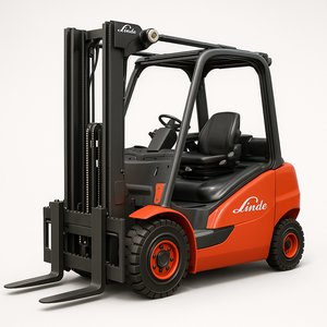
Original Illustrated Factory Operating and Maintenance Instructions for Linde Electric Forklift Truck Type 334-03.
Original factory manuals for Linde Forklift Trucks, contains high quality images, circuit diagrams and instructions to help you to operate and repair your truck
Covered models:
E10: SN after F2X334N
Format: PDF, 110 pages
Language: English
Include chapters:
1 Drive Motor
1.1 Traction motor
1.1.1 Checking and replacing of carbon brushes
2 Drive gearbox
2.1 Changing of gearbox oil
2.2 Regreasing of the turntable bearing
2.3 Gearbox setup
2.4 Motor pinion
2.4.1 Dismounting of motor pinion
2.4.2 Mounting of motor pinion
2.5 Mounting of traction motor to the gearbox
2.6 Replacement of the drive unit
3 Truck setup
3.1 Tightening torques
4 Steering system
4.1 Setting of the steering chain tension
4.2 Replacement of potentiometer of the steering position indicator
5 Operating elements
5.1 Brake actuation
5.1.1 Brake cylinder positions
5.1.2 Setting of the brake
5.1.3 Bleeding of the brake
5.2 Multi-function lever (MFL)
5.2.1 Mounting of the MFL
5.2.2 Basic calibration of the MFL p.c. board
6 Electrical system
6.1 Introduction
6.2 Survey of the electrical system
6.3 Control current fuses
6.4 Connector location
6.5 Digital controller 1A1
6.5.1 Connectors of the digital controller
6.5.2 Power section of the digital controller
6.5.3 Connection of revolving light and/or acoustic warning
6.5.4 Mounting of the controller
6.6 Truck diagnosis
6.6.1 Controller data and current faults
6.6.2 Fault memory
6.6.3 Measured values
6.6.4 Adjustments
6.6.4.1 Truck parameter
6.6.4.2 Battery type
6.6.4.3 Hour meter function etc.
6.6.4.4 Calibration of the joystick handle (multi-function lever) - traction
6.6.4.5 Calibration of the joystick handle (multi-function lever) - lift
6.6.5 Store parameter
6.6.6 Load parameter
6.6.7 Loading default settings
6.7 Battery discharge indicator and operating hour counter
6.8 Battery charger (special equipment)
6.9 Circuit diagram
7 Hydraulic system
7.1 Valve block
7.1.1 Setting of the pressure relief valve
7.2 Pump motor
7.3 Hydraulic functions
7.3.1 Brake release
7.3.2 Brake released
7.3.3 De-activation of the brake
7.3.4 Lifting
7.3.5 Lowering
7.3.6 Forward tilting
7.3.7 Backward tilting
7.3.8 Side shift right
7.3.9 Side shift left
7.3.10 Steering right
7.3.11 Steering left
7.3.12 platform lowering
7.3.13 Platform lifting
7.4 Oil level switch in the hydraulic reservoir
7.5 Hydraulic diagram
Need Help?
Our support team is here to help you with any questions.
Guaranteed
- 30-day money back guarantee
- Secure encrypted checkout
- Lifetime access to downloads
- Free updates included
$16.99
Download Now
Related Products
You might also be interested in these
Ready to Start Your Repair?
Get instant access to professional repair information. Download now and start fixing today.
$16.99